Support: Documentation - Assembling your structure
The profile system is easy to process and quick to assemble. Its flexible and modular construction means it can be easily modified and is reusable at any time.
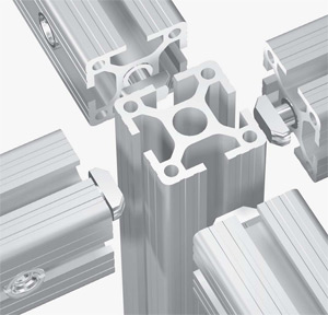
Using Connectors

See below the example of connecting two profiles 40×40 with one standard connector.
1. Insert the cross bushing.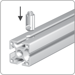
|
2. Push in the anchor.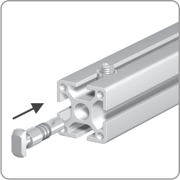
|
3. Tighten the anchor a little.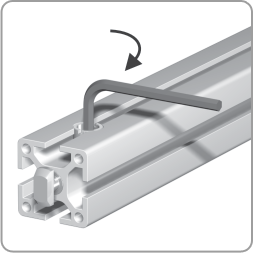
|
For the optimal assembly of the profiles, the connector is to be installed in such a way that the neck is flush to the profile front side.
4. Push in sideways and turn the profile:
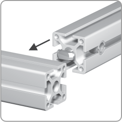
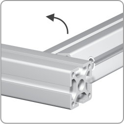
or push in front sided:
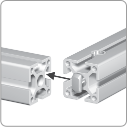
5. Tighten the setscrew.
Before mounting debur core hole.
Assembly Instruction
After you have made an order for the frame construction, you will receive frame installation specification, i.e. assembly instruction.
Assembly instruction is aimed to help you with your frame installation and contains the following useful information:
- Fully assembled view
- Exploded view
- Enlarged exploded view
- Legend (frame elements specifications).
Fully assembled view
A fully assembled view shows the frame construction in an assembled state. The profiles are enumerated.

Exploded view
An exploded view of the frame construction displays all parts of the construction to be assembled, i.e. profiles and connectors (anchors and cross bushings). All parts are enumerated.

E.g. 7C1 stands for the first connector of profile No. 7; and 7C2, for the second one.
Enlarged exploded view
An enlarged exploded view divides a construction into columns and rows and presents a more detailed view of how to assemble the frame construction.
Legend
A legend lists all parts used in the frame construction and presents a short description of each: profile model and length, connector model, etc.


